Quantum Gates and Circuits
Classical vs. Quantum Gates and Circuits

In classical computing, logic gates perform operations on bits. For example, the classical Not gate (see above) takes an input bit A and outputs the negation of A. These gates change the state of the input bit(s) to produce an output bit and serve as the building blocks of digital circuits used for classical computation.
In quantum computing, we have analogous gates that operate on qubits, but they are far more powerful due to the principles of superposition and entanglement.

The quantum version of NOT gate, known as the X gate, flips the state of the qubit, just like the classical NOT gate. However, it can also handle superposition states, a key feature of quantum computing.
Those quantum gates are combined to form quantum circuits, which are the building blocks of quantum algorithms. In this article, we’ll explore quantum gates and circuits in more detail.
Quantum Gates are Unitary Operators
In quantum mechanics, quantum states are represented as vectors in a Hilbert space, and transformation between quantum states are achieved using unitary operators.
Quantum gates in quantum computing are represented by unitary matrices that act on qubits. Let’s explore some key types of quantum gates.
Single-Qubit Gates
Single-qubit gates act on individual qubits.
X Gate
The X gate is the quantum equivalent of the classical NOT gate. It filps the state of a qubit. Its matrix representation is:
\[X = \begin{pmatrix} 0 & 1 \\ 1 & 0 \end{pmatrix}\]The X gate acts on the basis states $\ket{0}$ and $\ket{1}$ as follows:
\[\begin{align*} X \ket{0} &= \ket{1} \\ X \ket{1} &= \ket{0} \end{align*}\]Z Gate
The Z gate is another essential single-qubit gate. While there is also a Y gate (part of a gate family called Pauli gates), we’ll focus on the Z gate for now. These gates come from the Pauli matrices, which play a significant role in quantum mechanics (though we won’t dive into them here).
The Z gate leaves the basis state $\ket{0}$ unchanged but flips the sign of the basis state $\ket{1}$. Its matrix representation is:
\[Z = \begin{pmatrix} 1 & 0 \\ 0 & -1 \end{pmatrix}\]The Z gate acts on the basis states $\ket{0}$ and $\ket{1}$ as follows:
\[\begin{align*} Z \ket{0} &= \ket{0} \\ Z \ket{1} &= -\ket{1} \end{align*}\]This gate if often used in quantum algorithms to introduce phase changes, such as the sing flip in the state $\ket{1}$. These phase changes are a crucial feature that sets quantum computation apart from classical computation.
Hadamard Gate
The Hadamard gate is another important single-qubit gate that creates superposition. Its matrix representation is:
\[H = \frac{1}{\sqrt{2}} \begin{pmatrix} 1 & 1 \\ 1 & -1 \end{pmatrix}\]The Hadamard gate acts on the basis states $\ket{0}$ and $\ket{1}$ as follows:
\[\begin{align*} H \ket{0} &= \frac{1}{\sqrt{2}}(\ket{0} + \ket{1}) \defeq \ket{+} \\ H \ket{1} &= \frac{1}{\sqrt{2}}(\ket{0} - \ket{1}) \defeq \ket{-} \end{align*}\]By applying the Hadamard gate to a qubit in the state $\ket{0}$ or $\ket{1},$ the qubit is placed into a superposition of both states, commonly referred to as $\ket{+}$ and $\ket{-}$, respectively. This ability to create superposition enables powerful parallelism in quantum algorithms.
Multi-Qubit Gates
Multi-qubit gates are quantum gates that operate on multiple qubits simultaneously. These gates enable interactions between qubits, making them essential for building complex quantum algorithms.
Tensor Product of Single-Qubit Gates
Sometimes, we apply a single-qubit operation, such as the X gate, to one qubit in a multi-qubit system while leaving the other qubits unchanged. To achieve this, we use the tensor product of single-qubit gates. For example, consider a three-qubit system where we want to apply the X gate to the first qubit while leaving the second and third qubit in their original states:
\[\prths{X \otimes I \otimes I} \ket{0} \otimes \ket{0} \otimes \ket{0} = \ket{1} \otimes \ket{0} \otimes \ket{0}\]Here, $X \otimes I \otimes I$ represents the multi-qubit gate that acts on the three-qubit system, applying the X gate to the first qubit and the identity operation ($I$) to the second and third qubits.
However, not all multi-qubit gates can be expressed as a simple tensor product of single-qubit gates. Some gates create entanglement, a unique quantum phenomenon that links qubits such that the state of one qubit depends on the state of the others. These are called entangling gates and are crucial for the power of quantum algorithms.
Entangling gates enable the creation of states that cannot be factored into independent states of individual qubits. For example, the CNOT gate is an entangling gate that we’ll explore in the next section.
CNOT Gate
The CNOT gate (short for Controlled-NOT gate) is a two-qubit gate that flips the second qubit (the “target qubit”) if the first qubit (the “control qubit”) is in state $\ket{1}$. Its matrix representation is:
\[\text{CNOT} = \begin{pmatrix} 1 & 0 & 0 & 0 \\ 0 & 1 & 0 & 0 \\ 0 & 0 & 0 & 1 \\ 0 & 0 & 1 & 0 \end{pmatrix}.\]The CNOT gate acts on the basis states $\ket{00}$, $\ket{01}$, $\ket{10}$, and $\ket{11}$ as follows:
\[\begin{align*} \text{CNOT} \ket{00} &= \ket{00}, \\ \text{CNOT} \ket{01} &= \ket{01}, \\ \text{CNOT} \ket{10} &= \ket{11}, \\ \text{CNOT} \ket{11} &= \ket{10}. \end{align*}\]As shown, the CNOT gate flips the second qubit if the first qubit is in state $\ket{1}$. This behavior explains the name “Controlled-NOT gate”, as the NOT operation on the target qubit is controlled by the state of the control qubit.
Note: For now, we’ll focus on understanding the behavior of the CNOT gate, rather than diving into why its matrix takes this specific form.
Quantum Circuits
Similar to classical circuits, quantum circuits are composed of quantum gates that operate on qubits. These circuits form the foundation of quantum algorithms and are essential to design and implement quantum computations.
In quantum circuit diagrams:
- Qubits are represented as horizontal lines.
- Quantum gates are represented as boxes or symbols on these lines.
- The sequence of operations is shown from left to right, indicating that the time flows from left to right.
Let’s explore some examples to see quantum circuits in action.
Example: Single-Qubit Quantum Circuit with Hadamard Gate
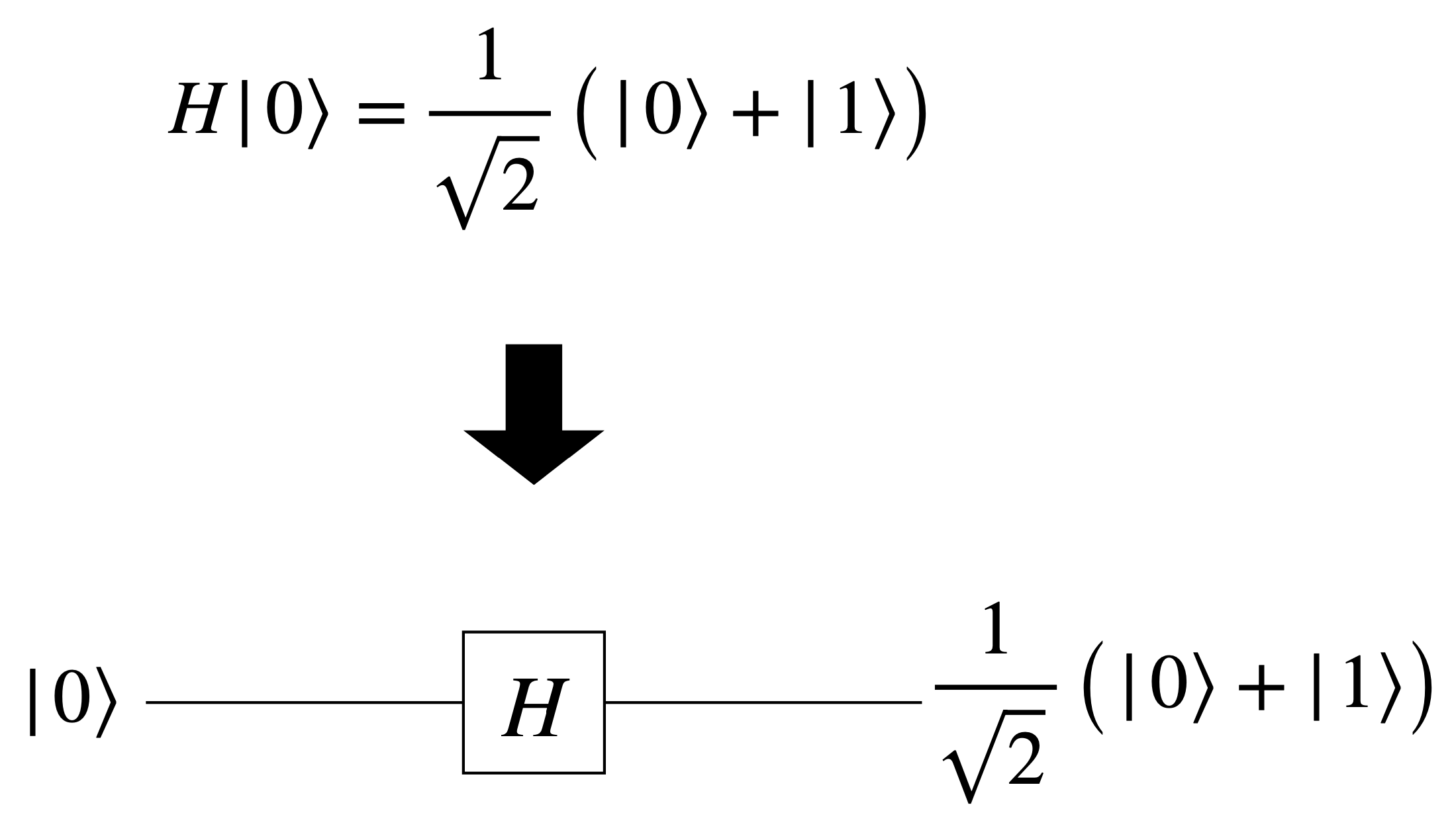
Consider a quantum circuit that applies the Hadamard gate $H$ to a qubit:

In this circuit, the input qubit starts in the state $\ket{0}$, and the Hadamard gate $H$ transforms it into the superposition state $\frac{1}{\sqrt{2}}(\ket{0} + \ket{1})$, or $\ket{+}$.
Example: Multi-Qubit Quantum Circuit with X Gate
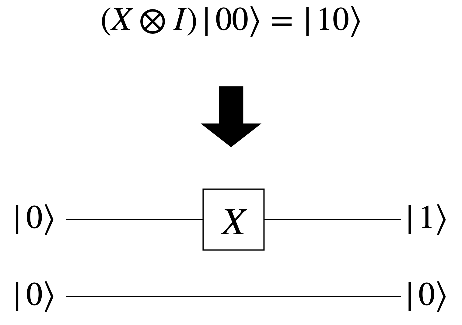
Now, let’s look at a quantum circuit that applies the X gate to the first qubit in a two-qubit system:

In this circuit, the first qubit is flipped from $\ket{0}$ to $\ket{1}$ by the X gate, while the second qubit remains unchanged.
Example: Multi-Qubit Quantum Circuit with CNOT Gate
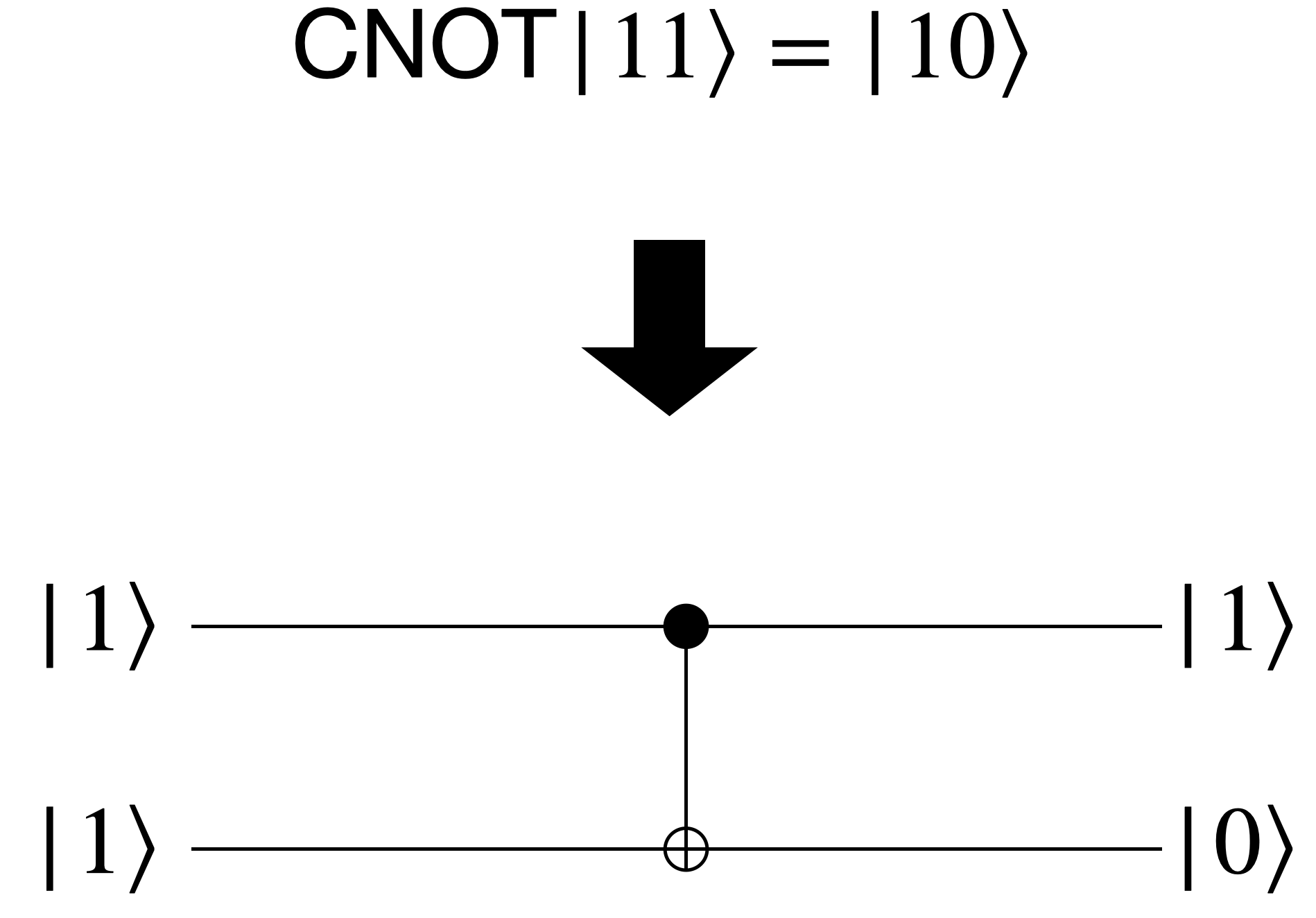
Finally, consider a quantum circuit that applies the CNOT gate to a two-qubit system:

In this circuit, the control qubit (top qubit, represented by a dot) determines whether the target qubit (bottom qubit, represented by a circle with a plus sign) is flipped by the CNOT gate. If the control qubit is in state $\ket{1}$, the target qubit is flipped; otherwise, it remains unchanged.
Quantum Algorithms
With quantum circuits, we can design and implement quantum algorithms that leverage the unique capabilities of quantum computing. These algorithms solve problems that are infeasible for classical computers, such as breaking cryptosystems, simulating quantum systems.
One notable application of quantum algorithms is in breaking cryptosystems. Quantum algorithms, such as Shor’s algorithm, can efficiently factor large numbers—a task that underpins the security of many encryption schemes. This capability highlights the power of quantum algorithms and the role in achieving quantum supremacy.
We’ll explore these groundbreaking quantum algorithms in future articles.
All images were drawn by the author.

Leave a comment